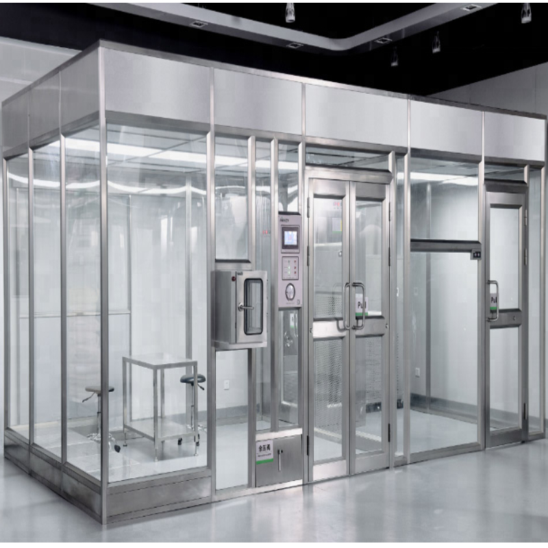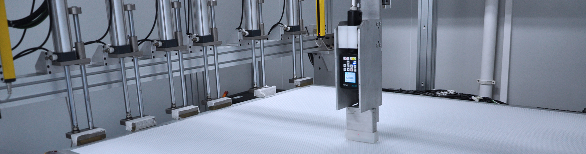
Mise en place d'un salle blanche pour semi-conducteurs De l'ISO 3 à l'ISO 6, une conception d'agencement précise est nécessaire, où la couverture FFU au plafond doit atteindre 85 % à 100 % pour l'ISO 3, 60 % à 80 % pour l'ISO 4 et 30 % à 50 % pour l'ISO 5, satisfaisant aux taux de renouvellement d'air et à l'uniformité du flux d'air laminaire.
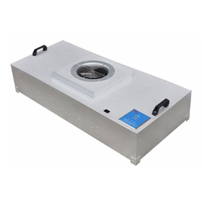
Ce guide technique traite de la conception technique et des calculs de CVC nécessaires aux usines de fabrication de semi-conducteurs. Il détaille les exigences de propreté ISO pour la photolithographie, la gravure et le conditionnement, et explique la formule mathématique pour Unité de filtre à ventilateur Ce guide traite de la couverture des plafonds (FFU) et aborde les problématiques critiques liées aux vibrations, au bruit et à l'uniformité du flux d'air. Il s'adresse aux ingénieurs d'usines de fabrication, aux concepteurs de procédés et aux consultants en CVC pour salles blanches qui doivent concevoir ou optimiser des installations de production de microélectronique ultra-propres.
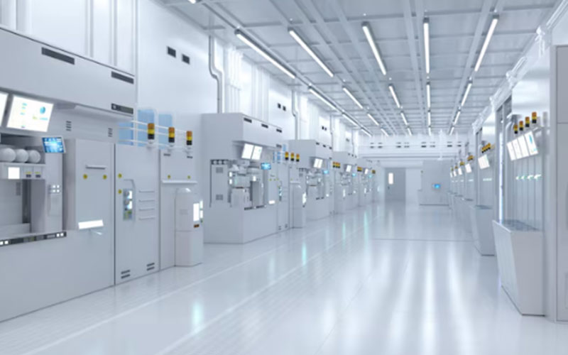
La fabrication de semi-conducteurs est l'un des procédés industriels les plus sensibles à l'environnement. Avec la réduction de la largeur des grilles de transistors à des échelles subnanométriques, une seule particule de taille inférieure au micromètre peut court-circuiter les pistes d'un circuit imprimé sur une plaquette de silicium, rendant ainsi une puce entière défectueuse. Par conséquent, les usines de semi-conducteurs sont divisées en plusieurs zones hautement contrôlées en fonction de la sensibilité du procédé spécifique :
Photolithographie (la « salle jaune ») : véritable cœur de l’usine, cette étape permet la projection des motifs de circuits sur les plaquettes de silicium. Compte tenu de l’extrême vulnérabilité de cette phase, les zones de photolithographie doivent répondre aux normes ISO classe 3 ou ISO 4. Ces zones requièrent un éclairage jaune strict (afin de prévenir toute exposition prématurée des produits chimiques de la résine photosensible) et un contrôle absolu de la contamination moléculaire atmosphérique (CMA) et des COV, ainsi que des particules.
Gravure et dépôt chimique en phase vapeur (CVD) : Le procédé d’enlèvement de matière et de dépôt de couches minces sur la plaquette exige une propreté de classe ISO 4 ou 5. Les particules présentes pourraient obstruer les gaz de gravure ou s’incruster dans les couches moléculaires du semi-conducteur.
Assemblage, conditionnement et tests (étape finale) : une fois les plaquettes découpées en puces individuelles, elles sont encapsulées dans des boîtiers de protection. Cette étape finale est moins sensible aux particules submicroniques et se déroule généralement dans des salles blanches de classe ISO 5 ou ISO 6.
| Classe ISO cible | Procédé typique de fabrication de semi-conducteurs | Couverture du plafond FFU | Qualité de filtration (EN 1822) | ACH recommandé | Type de flux d'air |
| Classe ISO 3 | Photolithographie (noyau d'exposition de nœud avancé) | 85 % à 100 % | U15 à U16 ULPA | 360 à 600+ | Unidirectionnel / Laminaire |
| Classe ISO 4 | Gravure chimique humide avancée, implantation ionique | 60 % à 85 % | U15 ULPA | 300 à 540 | Unidirectionnel / Laminaire |
| Classe ISO 5 | CVD, dépôt épitaxial, découpe en aval | 30 % à 60 % | HEPA H14 à U15 | 240 à 480 | Unidirectionnel / Laminaire |
| Classe ISO 6 | Conditionnement, test et stockage de photomasques de circuits intégrés | 15 % à 30 % | HEPA H14 | 60 à 120 | Non unidirectionnel |
Dans la fabrication des semi-conducteurs, les vibrations mécaniques constituent un problème majeur. Les machines de photolithographie utilisent des lentilles et des lasers de haute précision pour graver des circuits avec des tolérances nanométriques. Les vibrations des moteurs FFU fixés au plafond peuvent facilement se transmettre à travers la structure du plafond jusqu'aux piliers et au sol, provoquant un flou d'image lors de l'exposition des plaquettes.
Pour prévenir les problèmes de microvibrations, les usines de semi-conducteurs doivent mettre en œuvre plusieurs mesures d'ingénierie : 1. Isolation structurelle : La grille du plafond de la salle blanche doit être isolée structurellement de la structure en béton principale du bâtiment. Les unités de filtration frontale (FFU) doivent être suspendues à une grille métallique secondaire, totalement indépendante de la structure porteuse des équipements de lithographie. 2. Équilibrage dynamique : Chaque ventilateur et turbine de FFU doit faire l'objet d'un équilibrage dynamique de haute précision. Le degré d'équilibrage doit être conforme à la norme ISO 1940 G2.5, ce qui limite le déséquilibre résiduel et prévient les microvibrations. 3. Moteurs à faibles vibrations : Il convient de privilégier les moteurs EC sans balais. Ces moteurs fonctionnent de manière plus régulière et produisent nettement moins de vibrations que les moteurs à induction AC classiques, sujets au glissement électromagnétique et à l'usure physique du rotor.
Dans les salles blanches de semi-conducteurs, le maintien d'un flux d'air laminaire (unidirectionnel) est essentiel. La vitesse descendante doit être uniforme sur toute la surface du plafond afin d'éviter les turbulences, susceptibles de piéger les particules et de les faire se déposer sur les plaquettes de silicium exposées. - Norme de vitesse du flux d'air : Pour les classes ISO 3 à 5, la vitesse nominale du flux descendant doit être maintenue à 0,45 m/s (90 pi/min). - Limite d'uniformité du flux d'air : La variation maximale admissible de la vitesse du flux descendant au plafond est de ±20 % (de 0,36 à 0,54 m/s). Toute variation supérieure peut créer des différentiels de pression localisés, entraînant la formation de tourbillons de recirculation qui maintiennent les particules de poussière en suspension au-dessus des équipements de production.
KLC International fabrique des unités de filtration à ventilation haute performance spécialement conçues pour les environnements exigeants des usines de semi-conducteurs modernes. Nos systèmes sont conçus avec plusieurs caractéristiques techniques clés :
•Profil de faible bruit : les unités de flottation KLC utilisent des turbines optimisées sur le plan aérodynamique et des chambres acoustiques intégrées pour maintenir les niveaux de bruit en dessous de 53 dB(A) à une vitesse nominale de 0,45 m/s, ce qui est essentiel pour le confort des opérateurs dans les grandes usines contenant des milliers d'unités.
•Contrôle précis des vibrations : Chaque FFU de qualité semi-conducteur KLC est équipée de turbines en alliage d'aluminium à équilibrage dynamique certifiées conformes aux normes ISO 1940 G2.5, garantissant l'absence de micro-vibrations transmises aux outils de lithographie délicats.
•Technologie EC ultra-efficace : les unités de fusion KLC utilisent des moteurs EC à haut rendement atteignant jusqu’à 88 % d’efficacité, réduisant ainsi la production de chaleur et la consommation d’énergie du système CVC de l’usine.
•Système de contrôle de groupe RS485 : Les usines peuvent coordonner et surveiller plus de 10 000 unités de filtration depuis une salle de contrôle centrale. Le système prend en charge le protocole Modbus/RS485, permettant la surveillance en temps réel de la vitesse des moteurs, des pertes de charge et des défauts électriques, avec compensation automatique de la vitesse en fonction de la charge des filtres.
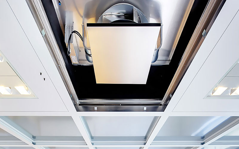
Une salle blanche de classe ISO 3 exige une couverture quasi totale de filtres ULPA pour maintenir un flux d'air laminaire vertical et unidirectionnel rigoureux. Avec une couverture de 85 % à 100 %, le plafond se transforme en une membrane continue de filtres ULPA, assurant un mouvement d'air descendant uniforme, comparable à celui d'un piston. Ce flux descendant constant élimine instantanément les particules des zones de lithographie sensibles, empêchant leur dispersion latérale.
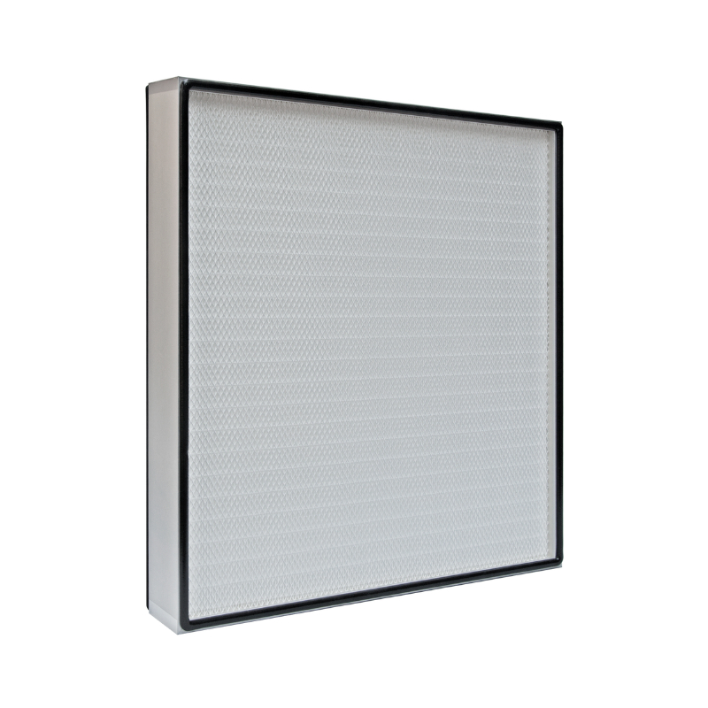
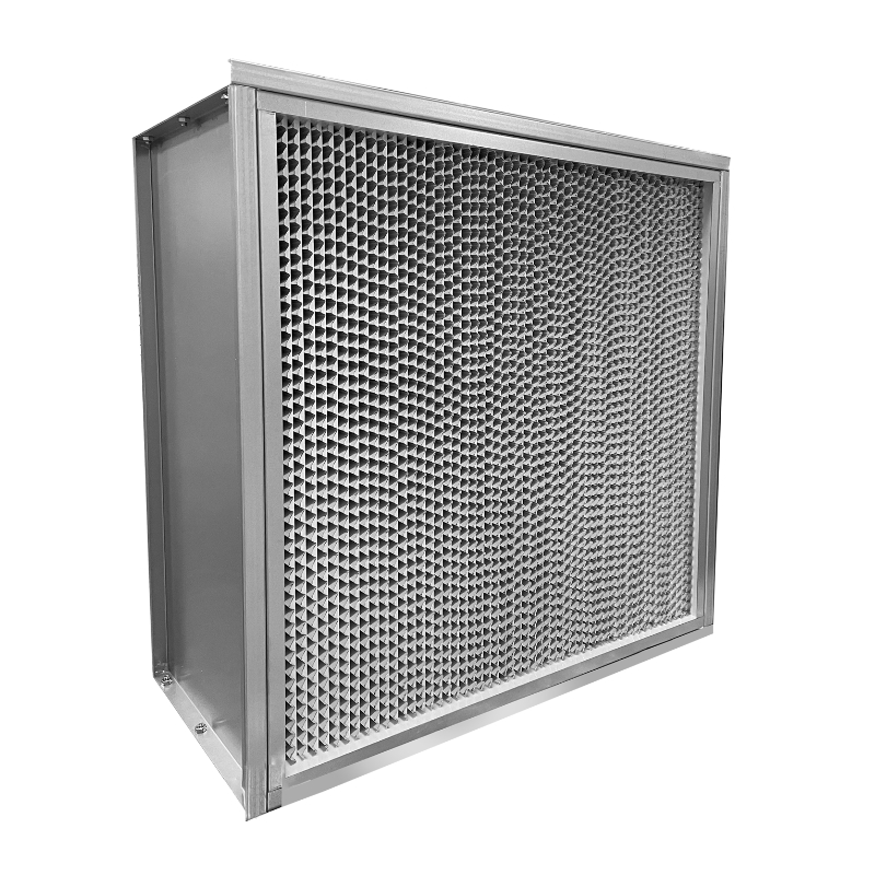
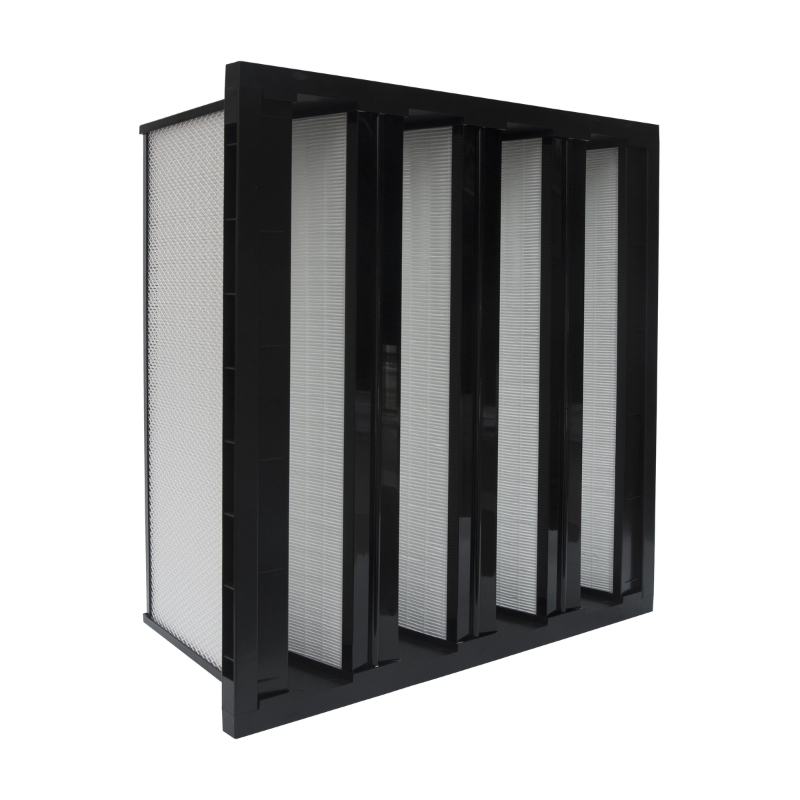
Un filtre HEPA H14 présente une efficacité ≥ 99,995 % pour les particules de 0,3 micron. Un filtre ULPA U15 (à très faible pénétration d'air) offre une efficacité ≥ 99,9995 % pour la taille de particule la plus pénétrante (MPPS), généralement comprise entre 0,12 et 0,17 micron. Dans les usines de semi-conducteurs de pointe, où des particules aussi petites que 0,1 micron peuvent provoquer une défaillance de la puce, des filtres ULPA U15 ou U16 sont requis pour les zones de lithographie et de diffusion en amont.
Les composés organiques volatils (COV) et les contaminants moléculaires aéroportés (CMA) peuvent réagir chimiquement avec les plaquettes de silicium ou se condenser sur les lentilles optiques des outils de lithographie, provoquant voile et défauts. Pour limiter ce phénomène, les unités de filtration frontale (UFF) de qualité semi-conducteurs sont souvent équipées d'un système de filtration à deux étages : une couche filtrante à charbon actif ou à épuration chimique sèche, placée en amont du filtre ULPA, permet de capturer les gaz organiques, les acides et les bases.
L'humidité cible standard est de 45 % HR ± 5 %. Si l'humidité descend en dessous de 40 % HR, de l'électricité statique peut s'accumuler, provoquant des décharges électrostatiques (DES) susceptibles d'endommager les circuits des microprocesseurs ou d'attirer des particules de poussière sur les plaquettes. Si l'humidité dépasse 50 % HR, la vapeur d'eau peut se condenser sur les résines photosensibles chimiques, entraînant des défauts d'adhérence et favorisant la corrosion des couches métalliques des circuits.
L'équilibrage manuel de milliers d'unités individuelles est impossible. Les ingénieurs utilisent des systèmes de contrôle de groupe numériques connectés à des unités de ventilation à moteur EC. Le système de contrôle communique via RS485 ou Ethernet, permettant aux techniciens de définir la vitesse d'air cible pour différentes zones. Le système ajuste ensuite automatiquement la vitesse de chaque unité de ventilation et surveille les capteurs de pression afin de maintenir un flux d'air uniforme et équilibré dans toute l'usine.
Un plancher technique surélevé avec dalles perforées est essentiel au maintien d'un flux d'air laminaire. L'air descendant provenant des unités de traitement d'air (UTA) fixées au plafond traverse ces dalles perforées pour atteindre le plénum sous plancher, d'où il est aspiré vers le haut par des gaines de reprise latérales, puis renvoyé vers le plénum au plafond. Ce système empêche l'air de heurter un sol plein et de créer des recirculations turbulentes susceptibles de piéger les particules dans la zone de travail.
Les moteurs EC utilisent une commutation électronique au lieu de balais, éliminant ainsi l'usure mécanique et la production de poussière de carbone. Ils fonctionnent également à une température beaucoup plus basse, ce qui réduit la charge thermique sur les systèmes de refroidissement de la salle blanche. De plus, leur vitesse peut être modulée avec une extrême précision de 0 % à 100 %, permettant au système de contrôle du groupe de maintenir des débits d'air précis.
Les unités de traitement d'air KLC (FFU) utilisent une combinaison de turbines à équilibrage dynamique, de carters de ventilateurs légers en aluminium et d'isolateurs de vibrations internes en caoutchouc qui découplent le bloc moteur du boîtier de l'unité. Ceci garantit que les micro-vibrations résiduelles générées par le moteur sont absorbées à l'intérieur de l'unité, empêchant ainsi leur transmission à la grille de plafond ou aux parois de la salle blanche.
La conception d'une salle blanche pour semi-conducteurs exige un équilibre précis entre filtration haute performance, flux d'air uniforme et contrôle rigoureux des vibrations. Pour garantir la conformité de votre usine aux normes ISO 3 à ISO 6 sans compromettre les rendements de production, collaborez avec un fabricant capable de fournir des unités de filtration à moteur EC haute performance avec systèmes de contrôle de groupe intégrés.
Pour des équipements de salles blanches pour semi-conducteurs haute performance, à faibles vibrations et économes en énergie, découvrez la gamme complète de produits de KLC International. VisitezKLC Internationalpour consulter les spécifications techniques, télécharger les dessins CAO FFU et consulter notre équipe d'ingénierie d'application en microélectronique.



 Réseau IPv6 pris en charge